
Car OBD2 Activation Diagnostic Test Tool Automotive IPC GSM EPB EPS BMS ABS/ABR System Test for Benz BMW Audi VW Landrover Ford
 Security Payment
Guard your secure payment with SSL.
 Delivery Policy
Handling time with 24 hours.
 Return Policy
30 days free return, 3 months exchange, 3 years warranty.
Note:This test has compatible range,before buy,please send message to me about your car model and year.
Car OBD2 Activation Diagnostic Test Tool Automotive IPC GSM EPB EPS BMS ABS/ABR System Test for Benz BMW Audi VW Landrover Ford
Introduction:
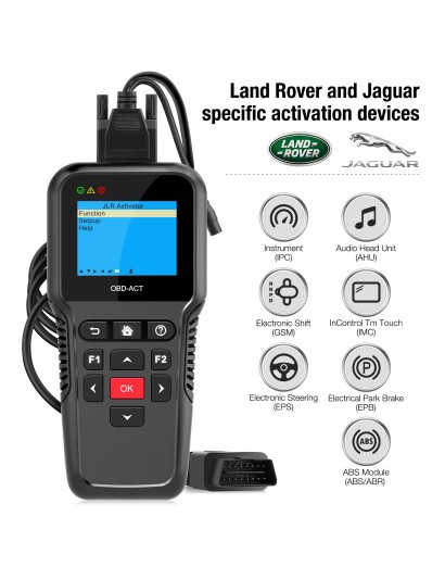
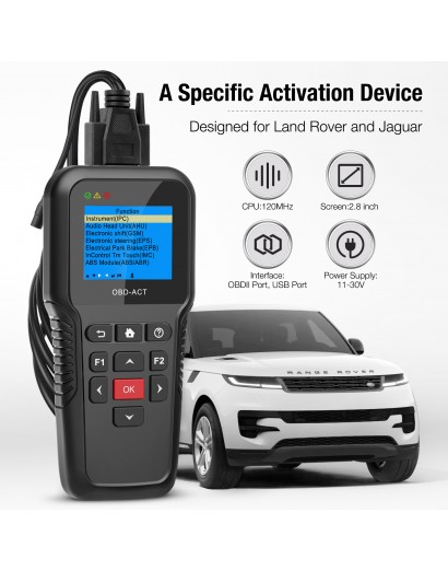
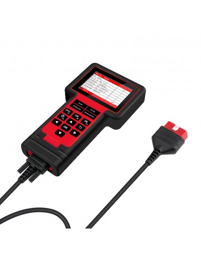
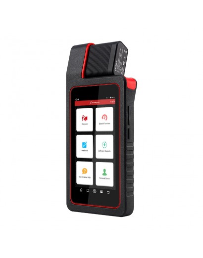
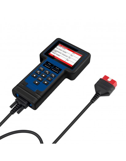
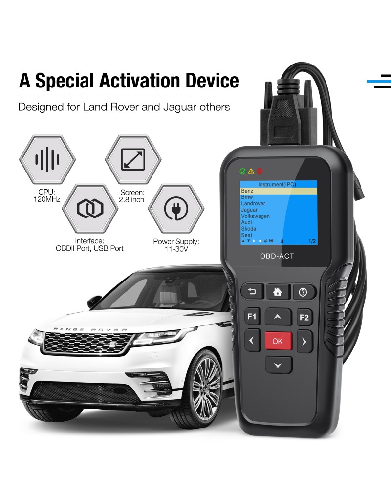
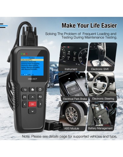
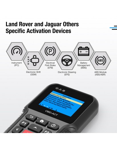
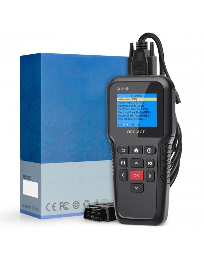
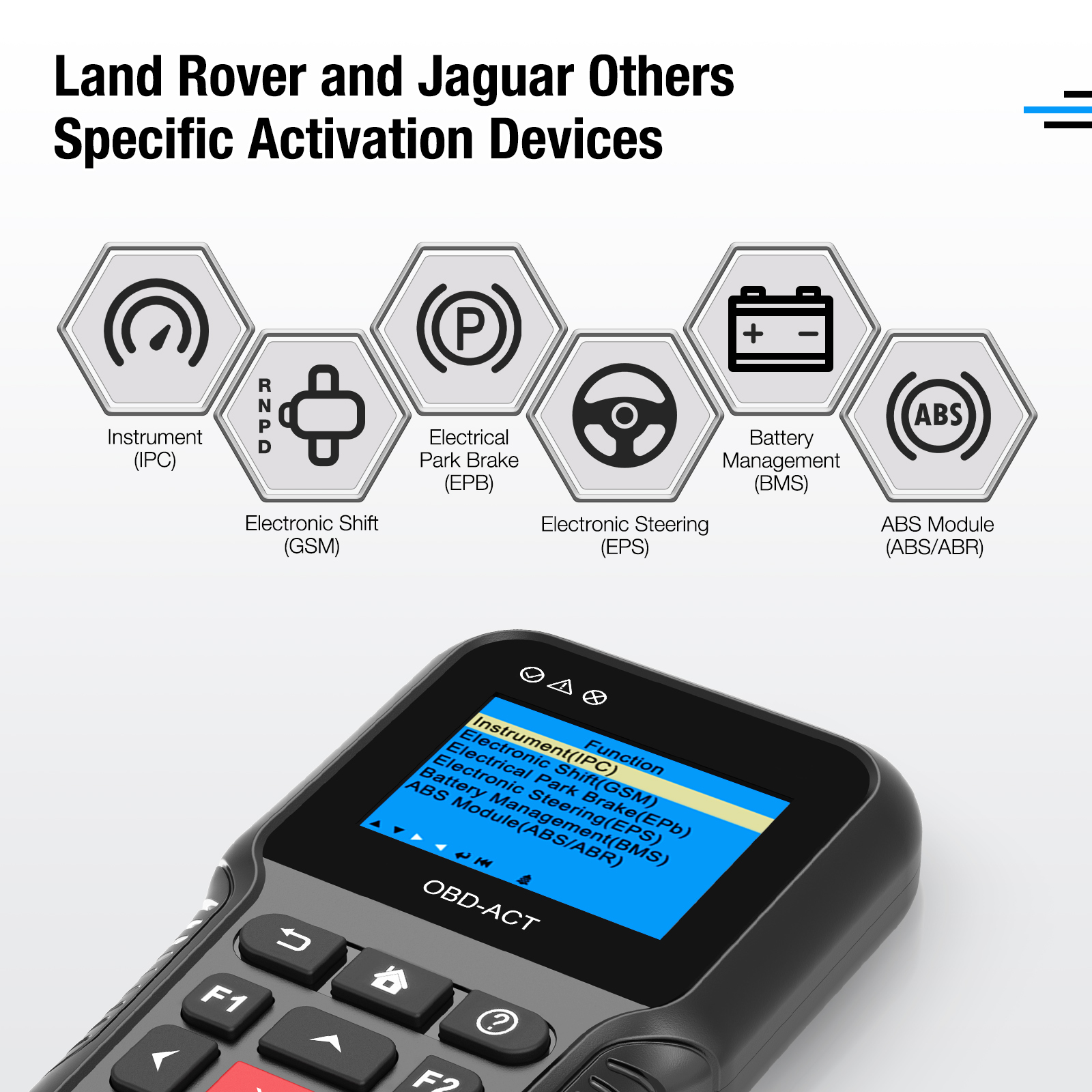
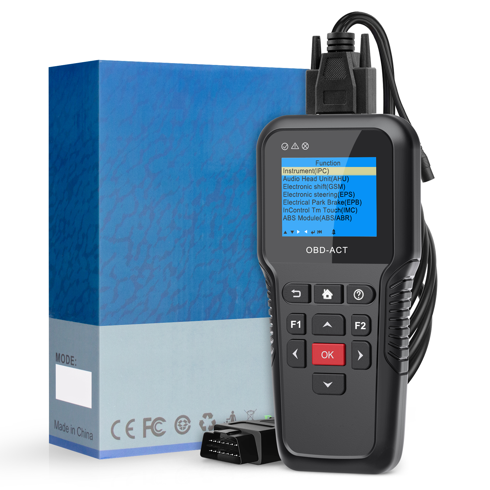
Multi Function Activator (ACT102) is a multi function activation devices. It supports Instrument (IPC), Electronic Shift (GSM), Electrical Park Brake (EPB), Electronic Steering (EPS), Battery Management (BMS), ABS Module (ABS/ABR) activation
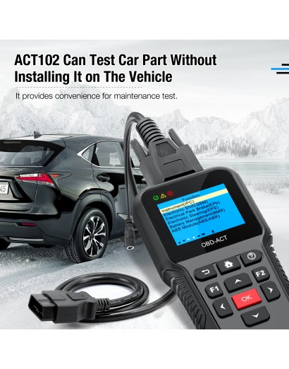
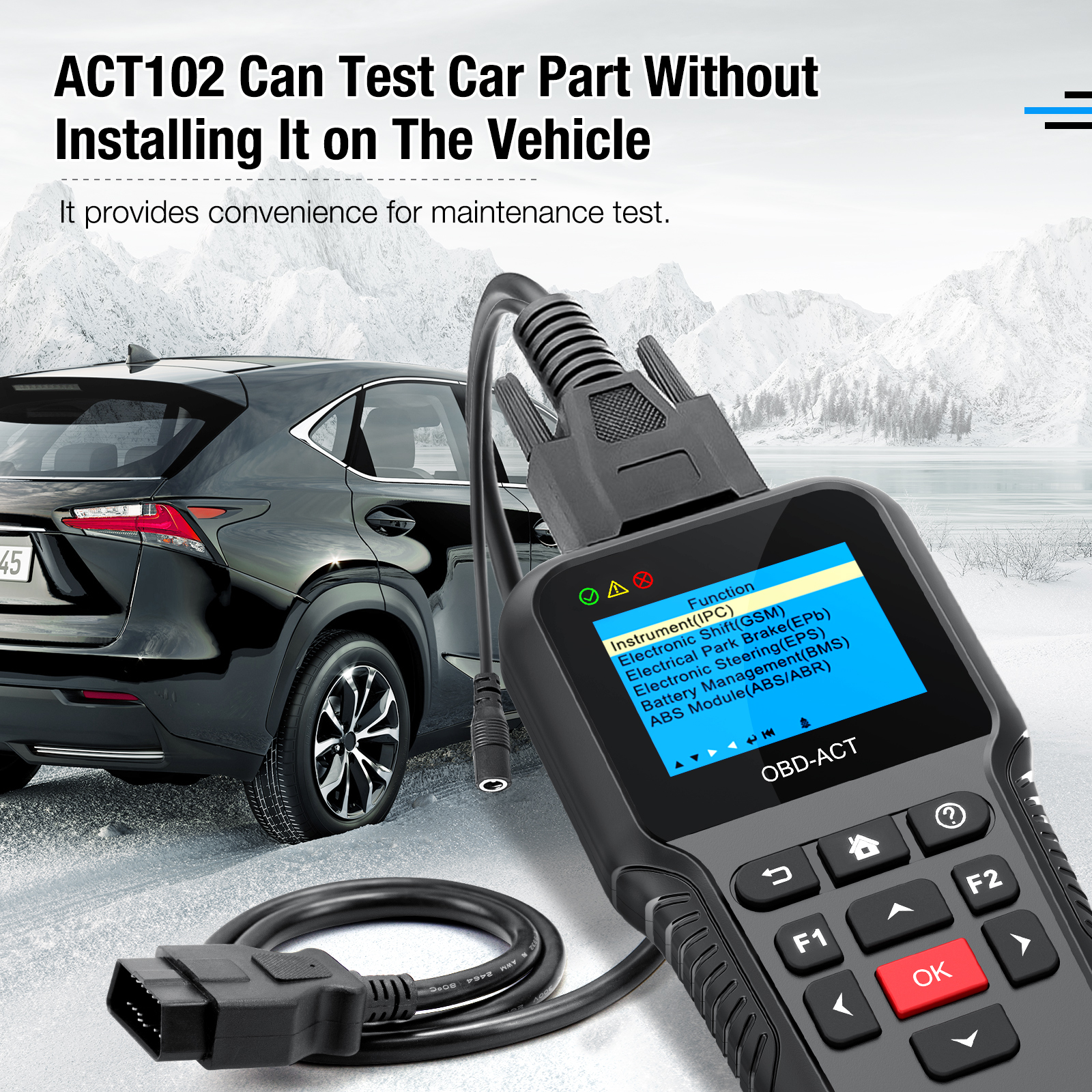
ACT102 can test car part without installing it on the vehicle. It provides convenience for maintenance test
1. Product Introduction
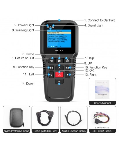
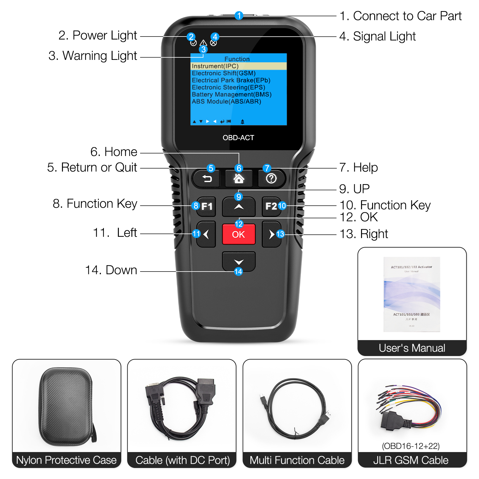
1.1 Device Introduction:
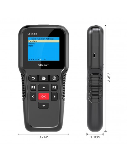
1.2 Technical Parameters
CPU: 120MHZ
Display: 2.8 inch
Resolution Ratio: 320*240
Interface: Test Port, USB Port
Power Supply: 11-30V
Storage Temperature: -30~90ºC
Working Temperature: -10~70ºC
Humidity: <90%
Dimension: 200*95*30mm
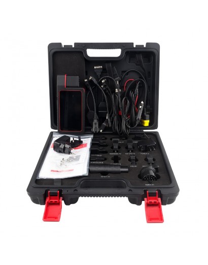
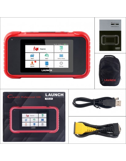
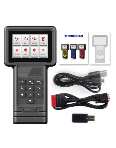
1.3 Configuration
Main Device
Main Cable (with DC Port)
Multi Function Cable
JLR GSM Cable(OBD16-12+22)
2. Electronic Shift(GSM) Operation:
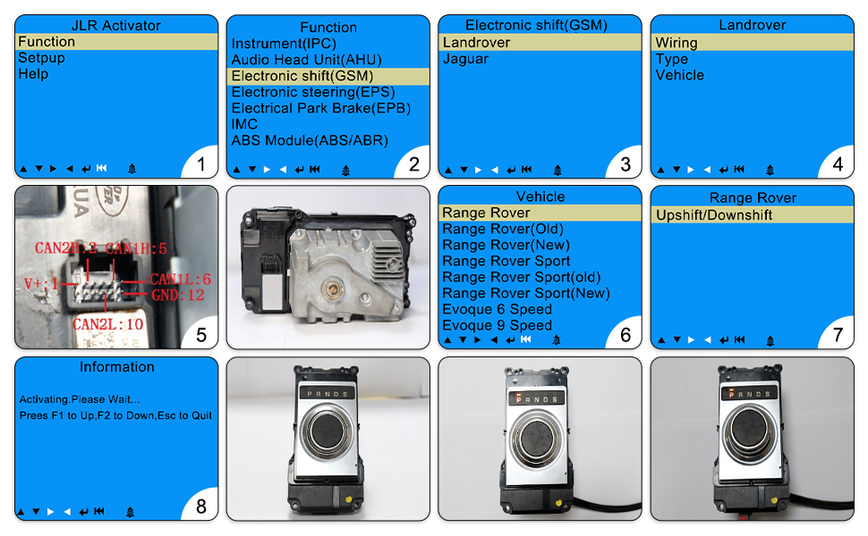
2.1. Use 12V DC power supply or battery, supply power to the main cable,shown in the following figure
2.2. Select【Function】,Press button 'OK', shown in the following figure
2.3. Select【Electronic Shift (GSM)】, Press button 'OK',shown in the following figure
2.4. Select【Landrover】, Press button 'OK',shown in the following figure
2.5. Select【Wiring】, Press button 'OK',shown in the following figure
shown in the figure below is range rover GSM,Please use the Multi Function Cable or JLR GSM Cable(OBD16-12+22).
2.6. Wiring complete,Press button ' ',Select 【Landrover】->【Vehicle】, Press button 'OK',shown in the following figure
2.7. Select【Range Rover】, Press button 'OK',shown in the following figure
2.8. Select【Upshift/Downshift】, Follow the prompts,shown in the following figure
Electronic Shift Status:not active, Light Off, Shift Down,shown in the following figure
Electronic Shift Status:Active, Light On, Shift Down, (Press Button 'F1' to Upshift),shown in the following figure
Electronic Shift Status : Active, Light On, Shift Up, (Press Button 'F2' to Downshift),When
Electronic Shift Status is Up, You can turn the shift to left or right;shown in the following figure
2.9.Test Complete
3.Electrical Park Brake(EPB) Operation:
3.1. Please use the original harness according to the wiring diagram provided
3.2. Refit the line as shown in the figure below;Connect CAN1H,CAN1L of device to CAN+,CAN- of Electrical Park Brake side
3.3.Electrical Park Brake side needs to be fixed with a fixture
3.4. Please use the car battery or use a DC power supply of about 10A; If the currrent not high enough,Electrical Park Brake can not work
3.5.Start the device, Select the corresponding vehicle type to test
3.6. If activation is successful,Press or pull the Electrical Park Brake button,Electrical Park Brake will release or Pull
3.7.Test complete.
4.Instrument(IPC) Operation:
4.1. Please connect the device and instruments with Multi Function Cable according to the provided wiring diagram
4.2. Please use the car battery or use a DC power supply of about 2A-3A,Connect to the Main Cable DC Port; It can supply power to instruments and device at the same time
4.3. Start the device, Select the corresponding vehicle type to test
4.4. If activation is successful, instruments light on
4.5.Test complete
5. .Electronic Steering(EPS) Operation:
5.1. Please use the original harness according to the wiring diagram provided
5.2. Use a multimeter to find out the Electronic Steering side CAN+ and CAN-,The socket Generally is 5pin.
5.3. Connect CAN1H,CAN1L of device to CAN+,CAN- of Electronic Steering side
5.4. Please use the car battery or use a DC power supply of about 10A;If the currrent not high enough, Electronic Steering can not work
5.5. Start the device, Select the corresponding vehicle type to test
5.6.Test complete.
6. Battery Management (BMS) Operation:
6.1. Please connect the device and battery module with Multi Function Cable according to the provided wiring diagram.
6.2. Please use the car battery or use a DC power supply of about 2A-3A,Connect to the Main Cable DC Port; It can supply power to battery module and device at the same time
6.3. Start the device, Select the corresponding vehicle type to test
6.4. If activation is successful,Battery Module will ouput voltage
6.5. Test complete.
7. ABS Module(ABS/ABR) Operation:
7.1. Please connect the device and ABS Module with Multi Function Cable according to the provided wiring diagram.
7.2. Connect CAN1H,CAN1L of device to CAN+,CAN- of Electronic Steering side.
7.3. Please use the car battery or use a DC power supply of about 2A-3A,Connect to the Main Cable DC Port; It can supply power to ABS Module and device at the same time.
7.4. Start the device, Select the corresponding vehicle type to test 7.5.Test complete.
8. Caution:
8.1.Electrical Park Brake(EPB),Electronic Steering(EPS),ABS Module(ABS/ABR) must use car battery or a DC power supply of about 10A.
8.2.Instrument(IPC),Audio Head Unit(AHU),Electronic Shift(GSM),InControl Tm Touch(IMC) can use car battery or a DC power supply of about 2A-3A.
8.3.Main Cable define: V+(#16) ,GND(#4) ,CAN+(#6) ,CAN-(#14).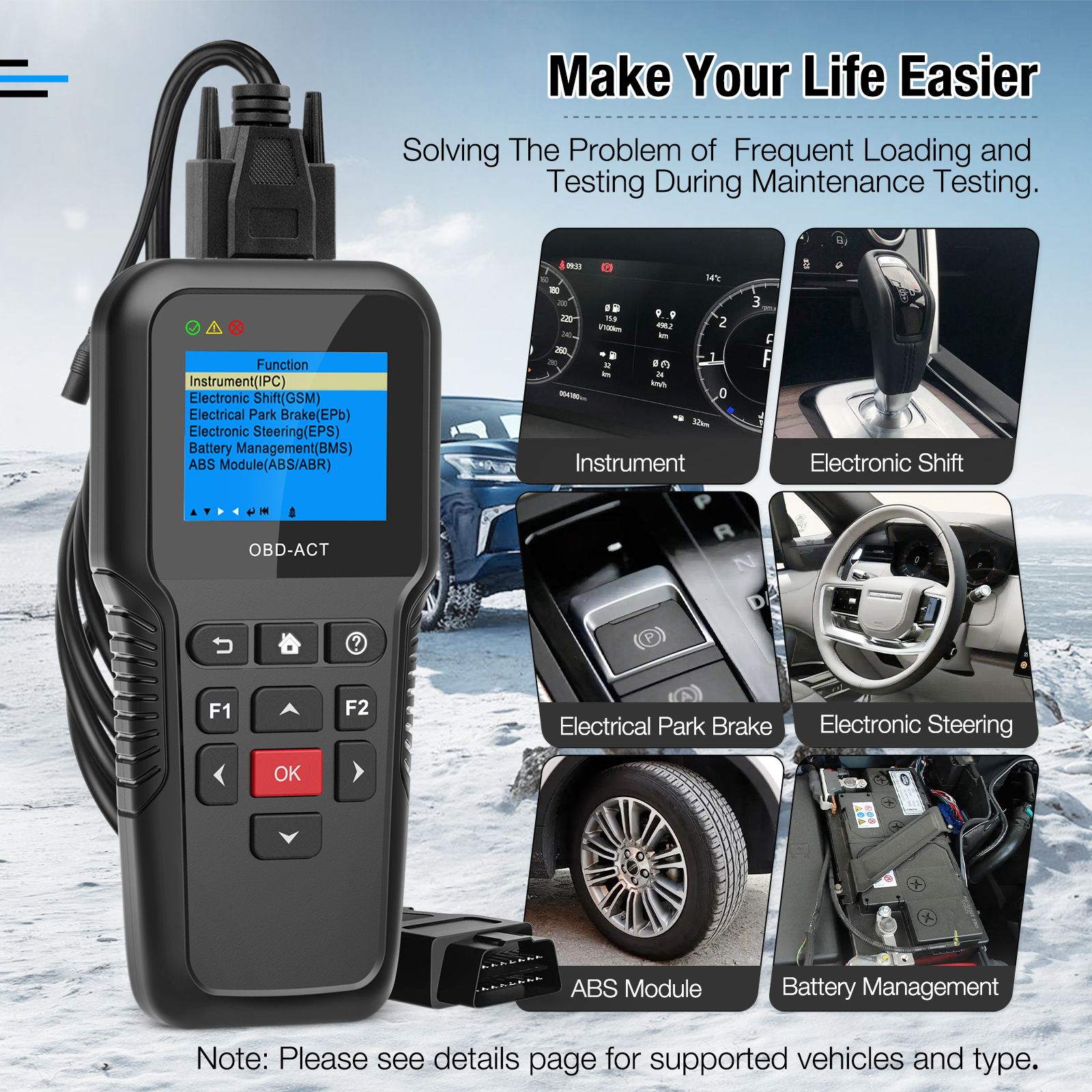

Car OBD2 Activation Diagnostic Test Tool Automotive IPC GSM EPB EPS BMS ABS/ABR System Test for Benz BMW Audi VW Landrover Ford